
Achieving Incident Free Project Execution Through The Use Of Effective Decision Support Tools (DST’S)
A Decision Support Tool (DST) is an operational barrier used to achieve desired and predictable project outcomes as part of an overall integrated risk management strategy.
GATE develops and implements DST’s to mitigate high risk exposure associated with project execution. When effectively developed and implemented, a DST can help the user to:
Set up an activity to achieve a high degree of safety prior to execution.
Operate during the activity in the safest way possible.
Support the operator in making better and more effective decisions when conditions during activity execution change.
By helping the user to make better decisions during stressful situations, there will be less reliance on the individual experience level of each user.
In its most simple form, a DST should comprise two sections:
Configuration & Setup
Operating Guidelines
DST CONFIGURATION SECTION
The objective of the Configuration Section is to identify the safe and advisory configurations of each activity for the particular operation being performed. Table 1 shows the basic dynamics of a Configuration Section, which explained in more detail below.

“Condition” row: This row contains the two important columns for this section: Best Setup Condition Column (green column) and Advisory Condition Column (blue column).
“Notification Protocol” row: This row explains whether the user should or should not notify a certain predefined group of people based on the user’s current condition.
“Action to Perform Based on Condition” row: This row explains what the user should do for each activity within the specific column.
Category Area: The rest of this section is dedicated to organizing individual aspects/activities of the operation into categories of similar concepts.
To set up the Configuration Section:
For each aspect/activity described in the categories, the safest setup for that particular activity is identified, typically determined through research and/or from experience in the activity, and is placed in the “Best Setup” condition column (the green column).
Any configuration deviating from the best setup is placed in the “Advisory” condition column (the blue column).
Each item should be verified prior to the execution of the related activity. The Configuration Section is not meant to prevent work from starting; however, if it is difficult or impossible to setup the activity according to the configurations in the green column, it is advisable to notify all parties and ensure that a risk assessment is performed to see how this variation may affect activity outcome.
DST OPERATING GUIDELINES SECTION
The Operating Guidelines Section provides actions that should be taken if certain failure scenarios impact the process or operation, causing a condition that represents a higher threat level. The Operating Guidelines Section uses the same fundamental dynamics as the Configuration Section, with some minor differences, including:
In this section, there are 4 different conditions: “Safe” condition and three different threat levels of escalating severity.
The actions to take for each threat level depend on the activity itself.
The rest of the document, as above, is dedicated to aspects of the activity that may change or failures that may occur during the execution stage.
Table 2 shows the basic dynamics of an Operating Guidelines Section.

DYNAMIC POSITIONING EXAMPLE
This example shows how several operational barriers need to be put in place to account for the failure modes of a single, but important, piece of equipment: The Dynamic Positioning (DP) system’s gyrocompasses. To start, here are a couple of quick facts about gyrocompasses (gyros):
Gyros are used by the DP system and the Global Positioning Systems (GPS’s) for accurate heading information.
Gyros can fail internally due to a design flaw or externally due to the loss of power supplies or communications systems.
Loss of all gyros will lead to an immediate loss of vessel position, since the DP system will no longer know the vessel’s position.
The importance of gyrocompasses to the stability of a vessel’s DP system is well known. Therefore, vessel systems are typically designed with multiple gyrocompasses and several power supplies to provide redundancy and prevent a total loss of all gyros.
The gyrocompass configuration for this example consists of two gyrocompasses, each having a primary and secondary power supply. The primary supply is the ship’s main Low Voltage (LV) system, while the secondary supply comes from two Uninterruptable Power Supplies (UPS’s), which can be thought of as big batteries. The gyrocompass power distribution table would look like this:

An effective DST must include an analysis of all of the interconnecting vessel systems. Therefore, we need to “zoom out” from the power supplies, and look for any configuration issues that could defeat the dual redundant gyrocompass setup.
This example vessel has a power distribution network that is split between portside (red) and starboard side (green). Each network has a Low Voltage (LV) and a High Voltage (HV) distribution. Two generators which are supplied from two different fuel oil tanks feed these power distribution systems.
IDENTIFYING FAILURE POINTS
With all of this information, we then look for any aspect within these interconnecting systems that could defeat the dual redundant gyrocompass setup. This system analysis leads to Table 3.

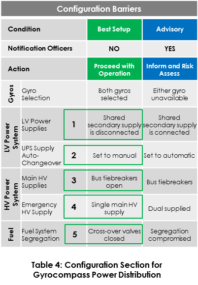
CONFIGURATION BARRIERS
Once the key potential failure points have been identified, configuration barriers must be created in order to help manage the risk potential. As shown above, the five key failure points have been mitigated with five relatively simple configuration changes shown in Table 4.
OPERATIONAL BARRIERS
After the vessel has been checked against the safest setup for the gyrocompasses, the operation can begin with greater confidence in the stability of the DP system. This being said, remember that during the operation, things may still fail.
Table 5 shows examples of line items that can be put in place to signal problems and possibly prevent the loss of all of the gyros. With this DST, the crew will be able to recognize the situation, and know exactly what to do after certain failure scenarios occur that cause a condition representing a higher threat level.

KEY TAKEAWAYS
DST’s can be designed to serve as effective operational barriers, especially when dealing with complex systems and high risk operations. For DST’s that are created for offshore, high risk operations, configuration barriers can help manage the impacts of previously undetected design flaws while operational barriers help to improve the crew’s confidence in making decisions during time-critical situations. Having this easy-to-use, industry-tested tool, reduces the need to rely on individual crew members’ personal experience.