Cost-Effective Gas Compression System Expansion Study

A winter-peaking natural gas storage plant undergoes a production expansion which includes infill well drilling and a gas compression system expansion. The original compression system consists of three gas engine – driven reciprocating compressors and one gas turbine – driven centrifugal compressor as shown in Figure 1.
The produced gas is sold to Pipeline A via Intermediate Pressure (IP) header and Pipeline B via High Pressure (HP) header. The operator sees a long-term demand increase and is considering adding a new compressor to the system. The operator brought GATE in to design a cost-effective gas compression system expansion.
Reciprocating Compressors Expansion
Three Ariel reciprocating compressors driven by Waukesha natural gas engines are compressing processed gas from Low Pressure (LP) to IP header to inject gas to Pipeline A.
With the operating conditions shown in Figure 1, the three machines operate with one suction unloader valve energized due to the driver power limit.
Material capacity increase would be possible if all the cylinders were loaded which means more power is required from the drivers. The operator considered replacing the engines.
GATE found a much less expensive solution to this power limit: Operate the Waukesha engines at a lower intercooler (I.C.) water temperature to obtain more power. The lower the I.C. water temperature, the denser the compressed air used for combustion which yields to more available power to the compressor.
Lower I.C. temperature can only be achieved during the winter season when the ambient air is cool enough to maintain the low I.C. water temperature. Since high capacity is required only for winter season, this should not be an issue. However, there are a few caveats in this modification:
The thermal regulator must be physically changed which may take a few hours but relatively easy.
The I.C. temperature must be returned to higher setpoint in the summer. Installation of a control loop will simplify this adjustment.
Centrifugal Compressor Expansion
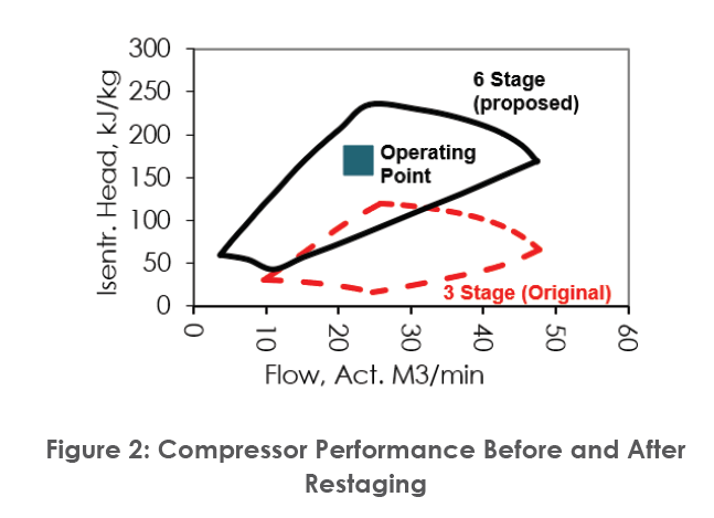
A Solar’s Centaur 50-driven gas compressor (C11) is installed with a three possible alignments: LP to IP, LP to HP and IP to HP. Despite those different possible alignments, it was originally designed for IP to HP compression. The overall compression system capacity can be increased by allowing C11 to compress gas from LP to HP and “spillback” some gas from HP to IP if necessary to meet Pipeline B gas demand via the spillback valve.
Compressor rewheel (also known as “restage”) is required to allow LP to HP compression as it requires higher head compared to the IP to HP compression. Solar’s modular design of impeller and diffuser in their compressors allows this performance change with relatively low cost and minimum intervention of the existing package. The compressor performance before and after restaging is shown in Figure 2.
Figure 2: Compressor Performance Before and After Restaging
A few design limits that need to be honored in such restaging process are: 1) discharge temperature limit, 2) gas turbine power limit and 3) aftercooler duty limit. In addition, it also requires some adjustments in the auxiliary systems such as surge control system.
Proposed Compression System Expansion
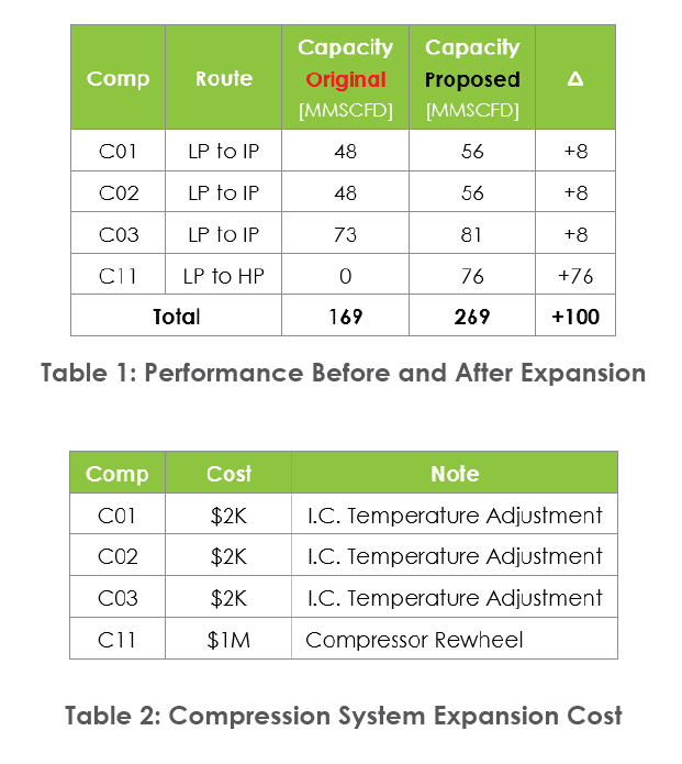
A 60% increase in the compression system capacity (Table 1) can be achieved with relatively low cost (Table 2) using the proposed compression system configuration shown in Figure 3. It demonstrates the system-approach (i.e., considering the system as a whole) yields to an elegant, fit-for-purpose, and cost-effective solution compared to adding an additional compressor that would have cost the operator approximately $150M + 2 years project duration.